

Success!
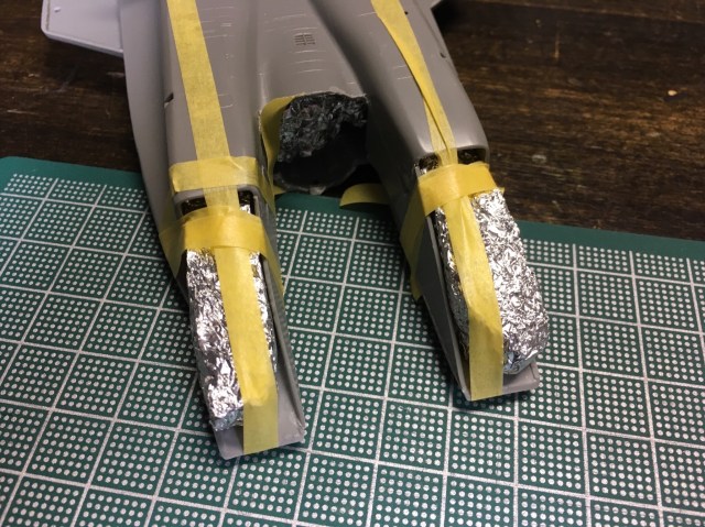
Seams cleaned up, pieces levered and reset, triangle piece added to get more sticking power. I also made a new foil jig to hold the opening wide for the fuselage after the horrible experience last time.
It was still a darn tight fit. Really tight. I tried using the cockpit assembly as a level to further pry open the fuselage while getting it snapped in there.
In the end, I realized there was just no way. I tried makeshift shoehorns, bigger wedge (it wouldn’t come back together once the fuselage was seated and was too firm to squish down further inside after the assembly was in place).
All to no avail. This kit beat me. I decided to shave off some of the bottom of the assembly and let it set with a gap underneath. The top looks good, the fit is tight and well-seated, and since it’s my model and no one but me will look on the underside, the damn thing is what it is. I’m going to enjoy it the way it is.
You’ve got to make your choices and choose your battles, or the modeling won’t be fun. Onward to the finish!
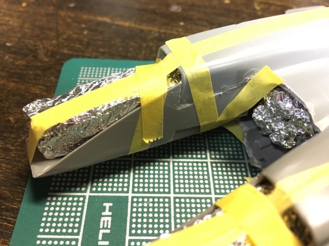
You might remember the last time that I’d put together the arrow piece with the foil jigs and Tamiya tape to pull things together into shape. Man, did it set well, Really firmly and pretty clean considering the warped nature of the fuselage in this kit.
It was all well and good until I tried to fit the canopy assembly. Even with the center foil jig prying things open (and I will end up leaving that foil jig in the middle once that assembly seats itself), it wouldn’t fit. I pushed to pry open further, pushed the assembly further, knowing it would need to snap into place, and…

Yes. Seams popped, the glue around the assembly sludged around… it’s a mess.
It’s back to the drawing board now. I need to clean up these seams and get things bound back together. Good thing I held onto those intake foil jigs so I don’t have to make them again.
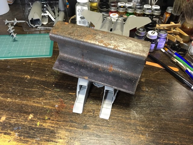
You’ll remember from last time, I got a piece of narrow gauge railroad rail that I can balance right to push down the arrow shapes into place. I was hoping that would hold things so I can move on to the next step. It went surprisingly well. There are gaps, but ones that should be hidden when the cockpit goes in.
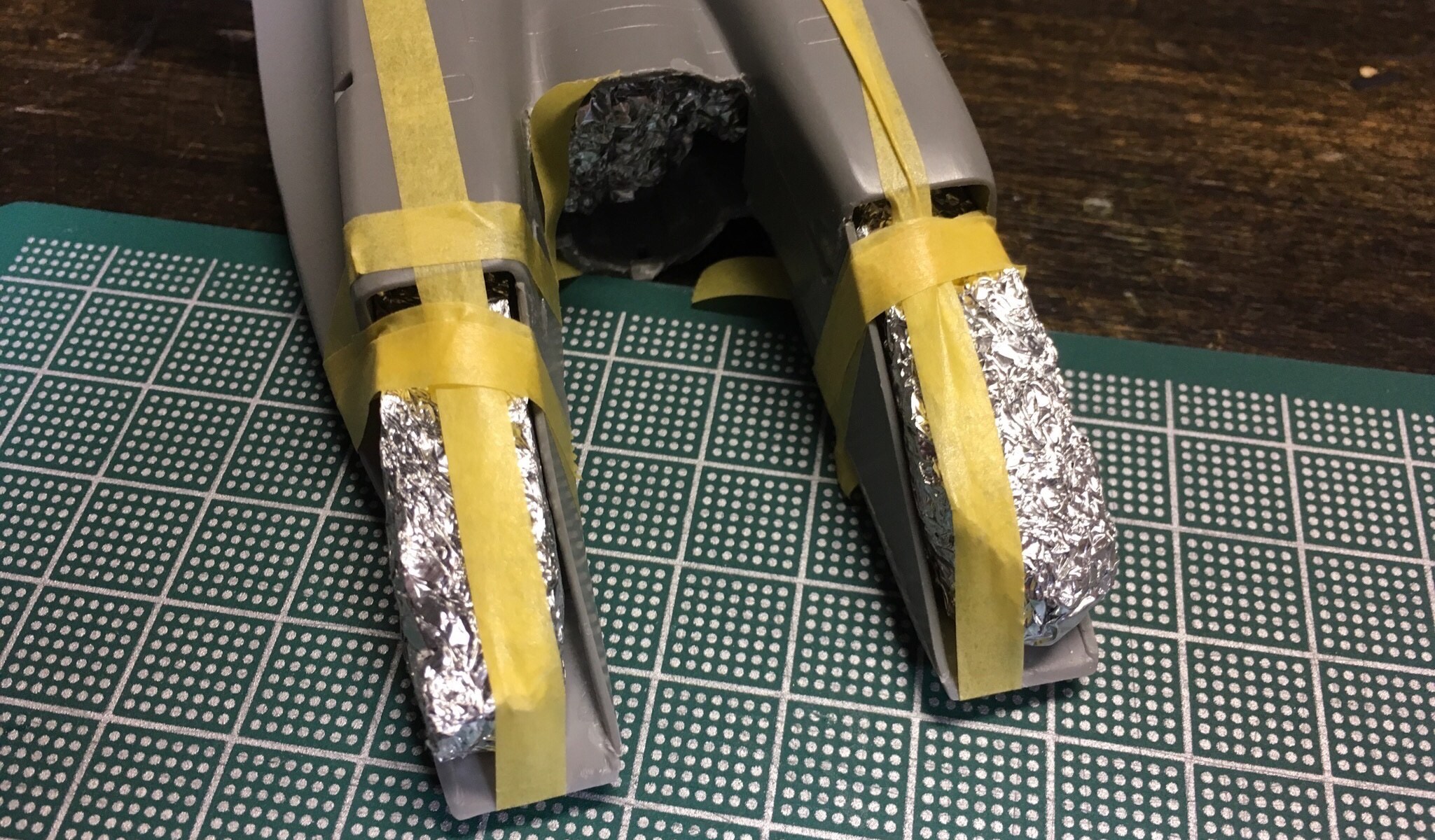
So now I’m going to use aluminum foil to create some custom ‘jigs’ that I’ll wedge into openings where I need the fuselage to keep the appropriate form. In some cases, they’ll also help to hold these panel pieces like the arrow shape and triangle shape where they belong from the inside. From the outside, Tamiya tape will pull in the pieces and act as tension clamps to pull things together.
First I’ll use it to secure the arrow pieces a bit better where they had gaps. When that’s set, I’ll use them for the triangle pieces on the outside of the intakes. You can see I’ve got foil jigs holding open spaces as needed.
These are very tightly bound ‘balls’ of aluminum foil I balled up and then literally hammered into shape. It takes a good amount of foil. You’ll see the two intake shaped ones and then the one in the middle of the fuselage is basically a cone shape. I may have to make a modified version of this one when I put the cockpit assembly in place to hold open the fuselage.
So far so good!


Oh boy, talk about bringing back memories!
I remember now how very poorly the jet intakes fit on this old Monogram mold. Yikes ahootie. It’s a serious balancing act to make these come together. I’m going to be doing well if I get them lined up at all, nevermind clean joints.
The main fuselage of the jet from behind the cockpit back to the exhaust is split between the top and bottom in the Monogram kit. These have to go together, set, and then have some intake pieces added to finish out that part of the model. This is where the fit of these parts really goes off the rails.
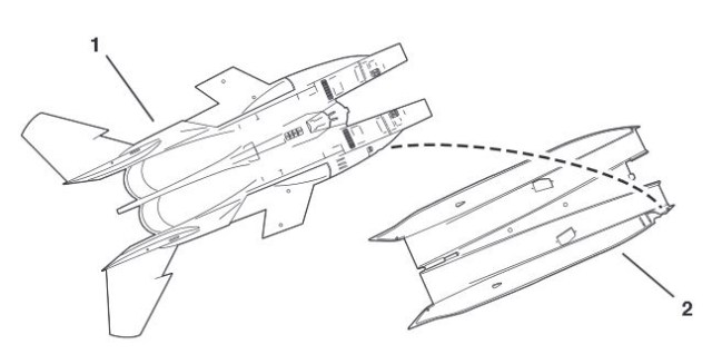 You’ll see in this first diagram, the fairly straightforward implementation of the two halves. I might have an old kit that was warped in storage over time, but I remembered this exact problem in my brand new 80s kit. The top have tends to ‘convex away’ from the interior and the bottom half tends to “concave inward”. This makes it not only tricky to line up the thin glued surfaces, but also very difficult to get things in place near the start of the intakes where the 20mm Vulcan canon resides. I remember gumming that up good when I did this back in jr. high. Big gap, because the pieces have to be held together well and:
- There’s too many places all the way around because both pieces tend to curl away from each other and
- Many of these edges just aren’t clampable – it’s too slippery or too rounded.
It takes either incredible patience and grip, or some inventive clamping. I used rubber bands to hold them together as best I could. These two halves need to be fully and firmly set for anything else to have a chance of going right with the intakes. And I still ended up with gaps so crappy, I either would have to start over or cut apart and reglue. And seeing as how the glue I use is pretty melty to plastic (testors liquid cement. I like it, not changing that), I’m going to live with it and move on. I model for me, remember?
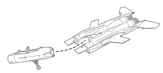
Modelers are nothing if not good planners. Once these halves are set, what you’ll notice immediately as you test fit the cockpit assembly intended to slide between them (diagram above), is that the front opening where the cockpit assembly is supposed to slide in, is much, much too small.
The convex top is bending down into the opening by almost 3/16 of an inch. Yes, you’re going to have to some how pry that son of a bitch open while you slide the cockpit assembly in, AND not break apart the multi-part intakes, let alone the fuselage itself.
Again, we’re going to have to get creative.


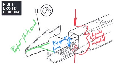
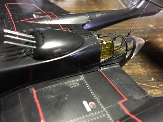
If that seemed cool, what’s next is even more awesome. You’ll fit an inside baffle glued flush with the front of the intake (as seen in the first image) and then add that arrow shaped piece to the inside wall of the intake. This arrow piece is close to where the cockpit assembly will slide in.
In fact, and you probably don’t know this now, but that arrow shaped piece will tend to sort of ‘snap in’ the cockpit assembly very tightly. So whatever you do with it, that sucker needs to be tight. And don’t worry too much about the looks of it outside the intake. The the cockpit assembly will be tight against it and hide most imperfections.
And seating that cockpit assembly will push mightily on it. It will seam as though it will crack it right out of where you solidly glued it having let it set for days. That’s a given for lots of things, but important to note here: that thin arrow-shaped panel has a correspondingly arrow-shaped opening for it to glue into the intake.
This means properly seated, it will be flush with both the inside and the outside of the intake. That’s a tight parameter to have for the rare flat piece that’s got exposed exterior on two sides.
But the real butt-kicker is, it doesn’t fit. In fact, it doesn’t fit in probably the worst way possible. It’s tight at the tip of the arrow (towards the opening of the intake) and open at the back (towards the rear of the intake). You can see this means a thin piece of styrene will have to:
- Sit on its edge
- Glued on almost all edges
- Prying the front of the intake open further to the front on one side
- Needing clamping to push the intake closed further to the back on the same side
- While not breaking out the main seam of the two fuselage halves.
 We’re going to have to get creative. Prying open and clamping down in the same area. That’s a neat thing. But it doesn’t stop there.
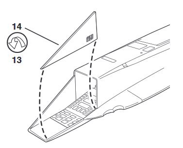 After that, there’s one more piece that forms the outward facing edge of the intake, a triangle piece. Not surprisingly, it doesn’t fit either. You have to choose between a gap on the top where it meets the intake’s top or the back where it meets the side.
We’re going to have to get creative.
First, I’ve got a piece of narrow gauge railroad rail that I can balance right to push down and temporarily curve to glue the arrow shapes into place. I’m hoping that will hold things so I can move on to the next step. Wish me luck.
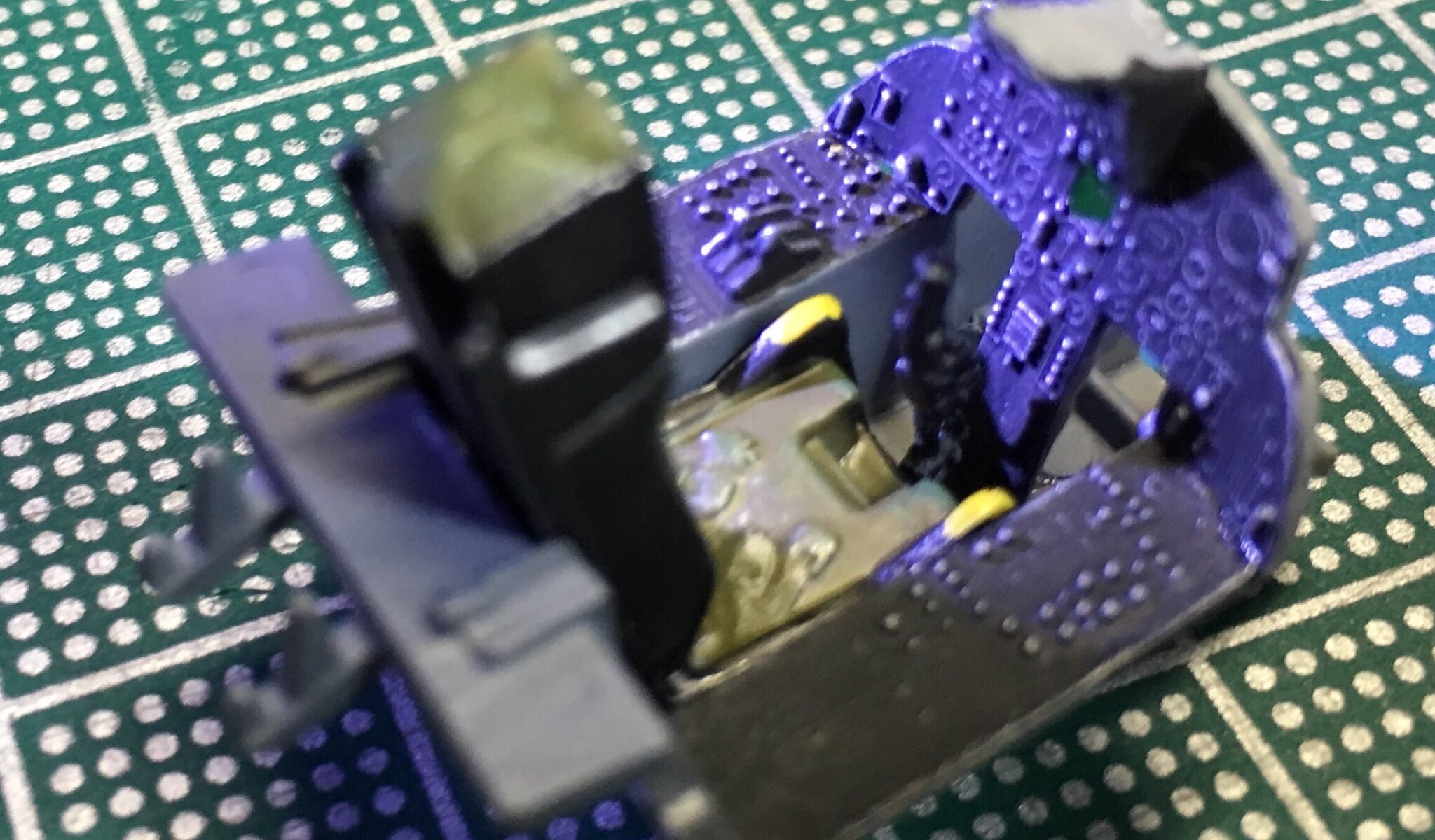
Started in on the cockpit, one of my fav parts of any aircraft model. It’s really fun to make a detailed cockpit, even knowing that if you have it displayed closed, you won’t see the detail later on.
It’s not only hard for me to see the details on scale models unaided, but after I’m done, the details I’ve worked on I can’t really see anymore either. I’m finding that taking pictures with my iPhone let’s me check my work later and keep some record of cockpits before they’re assembled. Also helps me remember how I did something later on.
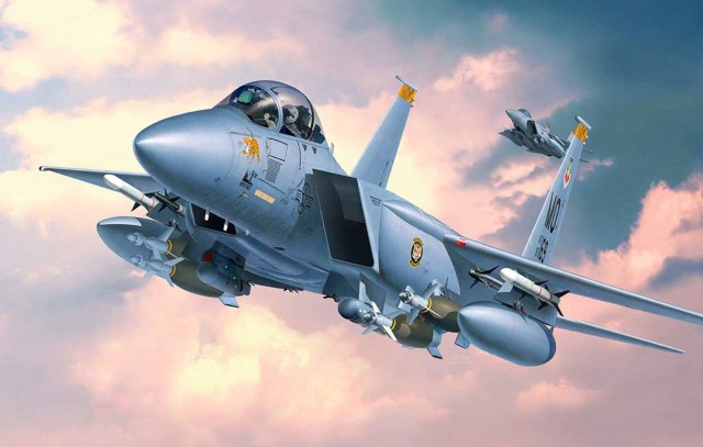
 I’m starting with some cockpit pictures like this one to let me get close to the real thing in color at least. I’m overwhelmed by the sheer volume of add on things from painted and unpainted photo etch parts, to decals, to fully made, even painted cockpits to drop in. Some of it seems interesting, but surprisingly more than I’d want to pay. I also like the fun of doing a cockpit with what the kit gives you and making the most of what you have. Most of all, for me this has to be fun and just for me, so my cockpits (and the whole aircraft for that matter) are an expression of my own enjoyment of the process and not some attempt to be 100% accurate or out-do what’s been done before.
To that end, I’m a dry-brush person for most cockpit things. Though I have to say, I’m pretty impressed and intrigued with the kind of cockpits people with airbrushes and a little planning can cook up, even with the cockpit the kit offers as is. I might have to look into that some day.


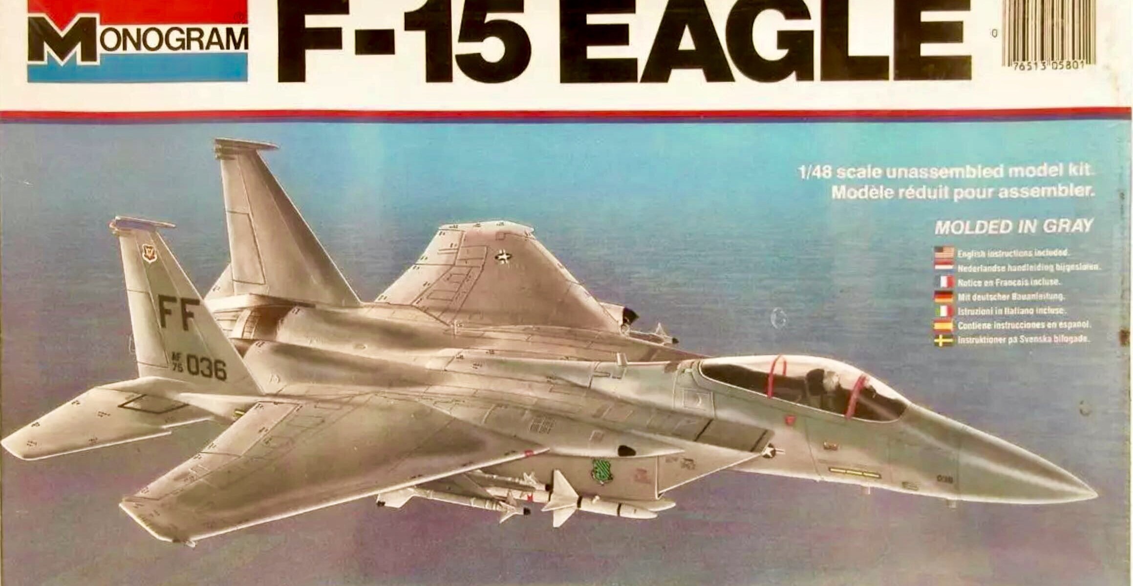
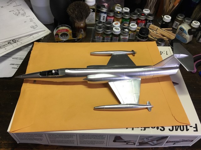
I did the model that got away first, the one back in the 80s I thought I might finish as my last. Now I’m revisiting and old friend with an old kit I bought off eBay.
This kit isn’t the really old one pictured above, but a 90s one. As I inspected what I bought, I see I failed to notice the canopy was missing from the pictures of the kit. So I have the actual 80s one on the way from another eBay seller so I can have the canopy. As much as I’d like to be able to make my own canopies, I don’t want to buy a vacuum system and don’t really like working with those anyway.
So, I’m excited to start this one I’m familiar with and see if it jogs any memories of back then, especially as it relates to building the kit, but also just in general. I’m off to a great start with the missing canopy, but hopefully the replacement is here soon and shouldn’t hold me back. I’m excited to build a jet fighter again!

The devil’s glosscote. If you model, don’t buy Krylon Colormaster Arcylic Crystal Clear. It destroys metallic finishes!!!!
Don’t do what I did.
I made a stupid assumption and didn’t read the label. I made the assumption that two Krylon spray products would work with each other. Well they don’t.
I don’t know what this hellish gloss coating is supposed to be good for if not for coating something you already painted. And ideally I guess the same company products. No, that’s not what it’s for. It’s for complete ruin of something you were really happy with. It’s for crushing dreams.
That’s pretty dramatic, but boy was I bummed. It just melted that gorgeous finish I had.
Remember this? The shining streak of aluminum? Gleaming image of the jet-age?

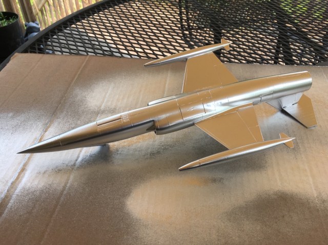
Yup, now it’s the hulking wad of pewter. The dream jet of Plymouth Rock puritans everywhere. What a steaming pile this has become. I put on the decals out of some spirit of putting this one to rest. I can’t possibly strip all that spraycan paint off and redo this.

This one crashed and burned.
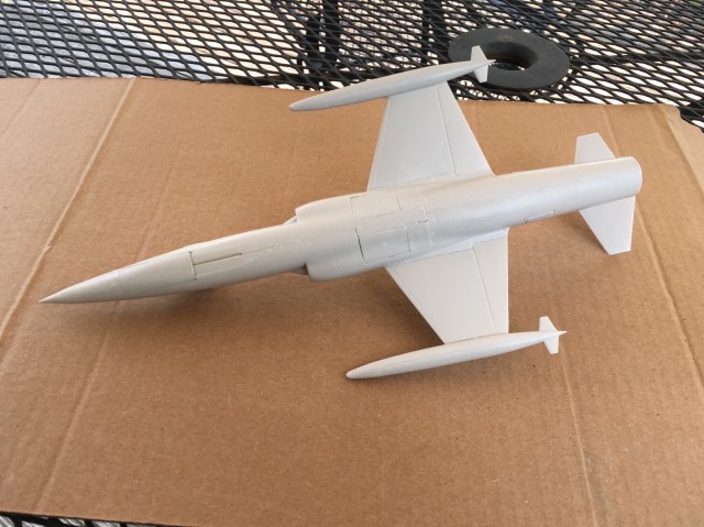
This Testors mold is clean and fits well for the most part, but not a lot of detail. The cockpit was so sparse of details, I didn’t think to take any pics of it. Maybe I’ll add a pic of what’s there once I have the exterior painted, but before the canopy.
It’s time to paint! I mentioned metal finishes have been a challenge for me. I hunted a long time for something that had good reviews for a really chromey metal finish. I want this to have a fresh from the factory look. I chose this silver paint from Krylon and then a Krylon seal to keep fingerprints from marring the shiney finish. That’s the theory anyway.
On to painting!
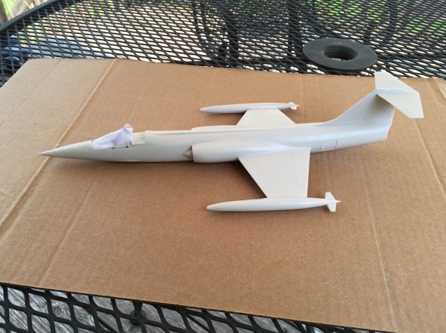
You can see there’s some challenges getting the wheels-up look with this kit. While the doors were well molded for being open, they didn’t close quite perfectly against each other. I had to glue one edge of each door, get it to soft set, then swing the door shut glueing the other edges . The doors are almost floating where they are.
Canopy masked and ready
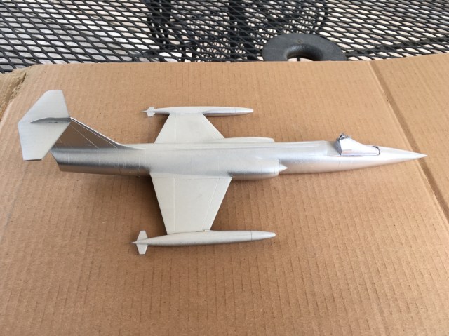
First sweeps of silver!
Wowsers, that’s pretty smooth and clean. I hope I can do this week on the much more visible top.
Wowsers! That’s the smoothest, nicest metallic finish I’ve ever done! Spray can finishes are so easy to over-do, and I got close with this one. but no runs and very little overspray! I’m very very pleased! Let this baby get good and cured and then I’ll get the clearcote on.

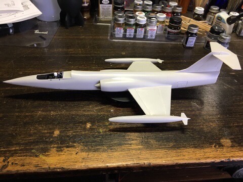
I’m pretty excited about this one. Got this kit for a steal off eBay. Looks in decent condition, but is kind of an old mold of the aircraft without much detail.
I’ve always done my aircraft wheels-down to place them on a shelf. This one I really want to do wheels up to make the most of the sleek look.
I’ve had limited success with metal finishes in the past. I know most real aircraft aren’t that shiny unless they’re at a tradeshow, but I’d like to make this one look as sleek and space-agey as possible! The F-104 just screams ‘JET-AGE’ and the transition to the space age. It looks like the kind of jet a 14 year-old boy would draw on their notebook.
Pretty excited for this cool slice of aluminum to take to the skies!
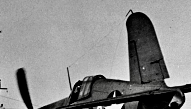
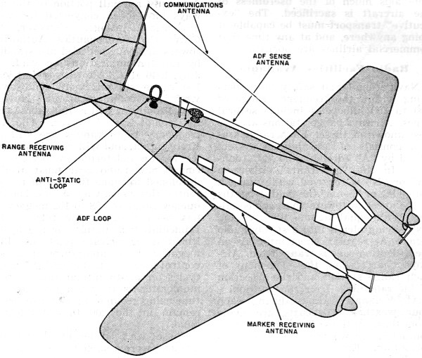
Often scale models of WWII aircraft will have antenna pegs molded to the fuselage or tail, meant to hold a wire communications antenna line as on the real aircraft. Sometimes these are pretty robust as on the Revell | Monogram B-17. Other times they can be pretty thin, flimsy, or already broken during shipping on smaller aircraft like fighters. They might be attached from the tail, fuselage, or a taller peg sticking up. Some older aircraft seem to be surrounded in these tensioned antenna wires.
Even the sturdiest pegs can easily snap off during seam sanding or when we’re doing our best just to handle the aircraft carefully. Most heartbreaking is having it happen when the model’s been long completed and you’re just dusting it or handling to reposition on the shelf. The safest route to repair is to spot sand or prep the area as needed, drill a replacement hole, and then replace it with a piece of styrene you fashion your self from leftover sprue or purchased styrene stock. This almost always works.
But what if I told you there was another way, a more dangerous way, but more durable way. You could replace with styrene and be right back where you started when you dust your model months later: a particularly disgusting predicament most modelers have faced — “I JUST FIXED THAT $#&^@! THING!”
You can turn that lemon into lemonade, but it’s going to take some careful work.
To replace the very tender pegs, you can use small wire segments. This is the crazy part: you’re going to make these wires a firm and permanent part of the aircraft to string a WWII era radio antenna on with some tension so it’s nice and straight, and takes the shelf-wear of dusting and handling for years.
I was fed up with this happening so I went for broke (which doesn’t always work out), kind of Bob Rossing my way into this idea. But with the gently-ripened patience that comes with age. Going for broke sometimes means thoughtful planning for what might have been a crazy plan. It’s hard to beat the durability of putting a metal peg in.
- Start by cutting thin wire segments to replace the pegs. I use floral wire or thin copper wire. You’ll want to choose a diameter of wire that matches the diameter of the plastic pegs you had, wire that stays rigid when pushed, and that will look in-scale. Make the segment long enough to handle comfortably, and capably with whatever pliers you’d use for something tricky or detailed.
- Remove alllll flammable chemicals, loose cloths, paper towels, kleenex, etc. from your worktop area where you’ll be doing this.
- Position the wire in your pliers in the position you’ll want it in to insert it into the spot where you’ll be replacing the antenna peg. Doing this will make sure you’ve got it ready to use comfortably after heating. Maybe even practice the movement you’ll need to insert the wire into the plastic.
- Using a small flame source (I used a culinary torch, but a candle can work), heat the end of your wire to red hot.
- Let the color go away, then patiently, but with purpose, put the hot end of the wire into the place where the plastic peg once was.
- Let the plastic firm up again before you release the position you’ve placed it in, so that if it’s so hot it melts lots of the plastic, there’s a better chance that plastic doesn’t move much and comes back to cool.
- Once the wire cools completely, use a side cutter (not your sprue cutter) to trim it down to the peg height you want. A little roughness on the top of the wire isn’t bad and will help keep the antenna you tie on from slipping off. I use paintable nylon thread for my wire – essentially very thin fishing line.
Tips
This is delicate, touchy work and several things could go wrong. Wobble that wire when it’s too hot, try to reposition it once it’s too cool, and you’ll either:
- go right through a part of the plastic you didn’t want to
- rip a larger hole in the plastic than can hold the wire in place
- shift the entire model as you try to insert the hot wire
- or push a warp into your plastic you can’t fix.
Try it out first on either a scrap piece from the same kit or the thinner number tabs on the sprue to get a feel for the melting action.
You’re probably working with a pretty much finished piece when you’re doing this. Think through the movement, practice it with a cool wire several times, and be sure to secure the piece you’re inserting the wire into very solidly so it doesn’t move on you.
Now for the antenna itself. I had 3 pegs on this airplane (two on each tail and a peg just above the radio seat in the back, making a V with the antenna line. Like in the diagram above.
- Tie the antenna to the first peg and put a drop of small drop of glue on it.
- Bring the antenna to the second peg in the middle and pull some tension as you give it a few wraps around the peg.
- Hold that steady and put another drop of glue to hold those wraps in place.
- Once it sets, wrap your final peg with several turns or tie it on if you can get the tension you want. Put spots of glue on this to hold as you did with the second peg. When it sets, you’ll find it holds well too.
- Touch up with paint to match.
If one of them doesn’t hold or you didn’t like how the antenna sets, you can carefully remove the antenna with some xacto knife finessing, a little sanding on the pegs and try again.
PROS:
- It’s a rock-solid hold for WWII antennas.
- It stays shelf stable through dusting and handlings.
CONS:
- You could damage your model in a way that is very hard to repair, especially when you’re nearly done.
Could you drill a hole and put the same wire in, glued in place instead of melted and still have the same durability?
Absolutely.
Is that what you should do instead of melting a hot wire into your beloved, mostly finished model?
Almost certainly, yes.
