F-15 Eagle – Jet intake challenges

Oh boy, talk about bringing back memories!
I remember now how very poorly the jet intakes fit on this old Monogram mold. Yikes ahootie. It’s a serious balancing act to make these come together. I’m going to be doing well if I get them lined up at all, nevermind clean joints.
The main fuselage of the jet from behind the cockpit back to the exhaust is split between the top and bottom in the Monogram kit. These have to go together, set, and then have some intake pieces added to finish out that part of the model. This is where the fit of these parts really goes off the rails.
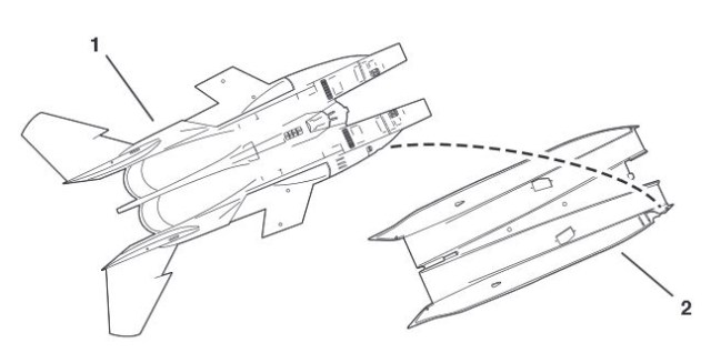 You’ll see in this first diagram, the fairly straightforward implementation of the two halves. I might have an old kit that was warped in storage over time, but I remembered this exact problem in my brand new 80s kit. The top have tends to ‘convex away’ from the interior and the bottom half tends to “concave inward”. This makes it not only tricky to line up the thin glued surfaces, but also very difficult to get things in place near the start of the intakes where the 20mm Vulcan canon resides. I remember gumming that up good when I did this back in jr. high. Big gap, because the pieces have to be held together well and:
- There’s too many places all the way around because both pieces tend to curl away from each other and
- Many of these edges just aren’t clampable – it’s too slippery or too rounded.
It takes either incredible patience and grip, or some inventive clamping. I used rubber bands to hold them together as best I could. These two halves need to be fully and firmly set for anything else to have a chance of going right with the intakes. And I still ended up with gaps so crappy, I either would have to start over or cut apart and reglue. And seeing as how the glue I use is pretty melty to plastic (testors liquid cement. I like it, not changing that), I’m going to live with it and move on. I model for me, remember?
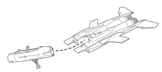
Modelers are nothing if not good planners. Once these halves are set, what you’ll notice immediately as you test fit the cockpit assembly intended to slide between them (diagram above), is that the front opening where the cockpit assembly is supposed to slide in, is much, much too small.
The convex top is bending down into the opening by almost 3/16 of an inch. Yes, you’re going to have to some how pry that son of a bitch open while you slide the cockpit assembly in, AND not break apart the multi-part intakes, let alone the fuselage itself.
Again, we’re going to have to get creative.


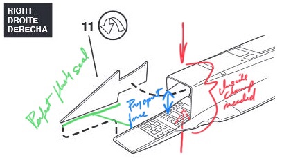
If that seemed cool, what’s next is even more awesome. You’ll fit an inside baffle glued flush with the front of the intake (as seen in the first image) and then add that arrow shaped piece to the inside wall of the intake. This arrow piece is close to where the cockpit assembly will slide in.
In fact, and you probably don’t know this now, but that arrow shaped piece will tend to sort of ‘snap in’ the cockpit assembly very tightly. So whatever you do with it, that sucker needs to be tight. And don’t worry too much about the looks of it outside the intake. The the cockpit assembly will be tight against it and hide most imperfections.
And seating that cockpit assembly will push mightily on it. It will seam as though it will crack it right out of where you solidly glued it having let it set for days. That’s a given for lots of things, but important to note here: that thin arrow-shaped panel has a correspondingly arrow-shaped opening for it to glue into the intake.
This means properly seated, it will be flush with both the inside and the outside of the intake. That’s a tight parameter to have for the rare flat piece that’s got exposed exterior on two sides.
But the real butt-kicker is, it doesn’t fit. In fact, it doesn’t fit in probably the worst way possible. It’s tight at the tip of the arrow (towards the opening of the intake) and open at the back (towards the rear of the intake). You can see this means a thin piece of styrene will have to:
- Sit on its edge
- Glued on almost all edges
- Prying the front of the intake open further to the front on one side
- Needing clamping to push the intake closed further to the back on the same side
- While not breaking out the main seam of the two fuselage halves.
 We’re going to have to get creative. Prying open and clamping down in the same area. That’s a neat thing. But it doesn’t stop there.
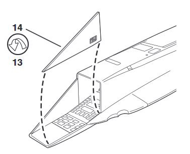 After that, there’s one more piece that forms the outward facing edge of the intake, a triangle piece. Not surprisingly, it doesn’t fit either. You have to choose between a gap on the top where it meets the intake’s top or the back where it meets the side.
We’re going to have to get creative.
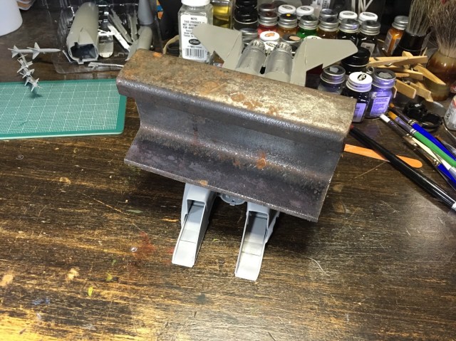
First, I’ve got a piece of narrow gauge railroad rail that I can balance right to push down and temporarily curve to glue the arrow shapes into place. I’m hoping that will hold things so I can move on to the next step. Wish me luck.